
- GOTRONIK PPHU
UL. BYSTRZYCKA 69C
54-215 WROCŁAW
NIP: PL8971671385 - E-mail:biuro@hantek.pl
- TelefonZamówienia: 511-048-814
Pyt. techniczne: 514 349 414 - Gadu Gadu75415537
- Godziny działania sklepuPN - PT 08:00 - 16:00


DSO1102B oscyloskop cyfrowy 2 x 100MHz
Dostępność: Aktualnie niedostępny
Koszt wysyłki: od 0,00 zł Dostępne formy wysyłki dla oglądanego produktu:Kurier GLS - 0,00 zł
Odbiór osobisty - 0,00 zł
Numer katalogowy: DSO1102B
Stan magazynowy: 
Stan produktu: Nowy
- Opis produktu
- Parametry techniczne
- Manual, oprogramowanie
- Recenzje produktu (0)
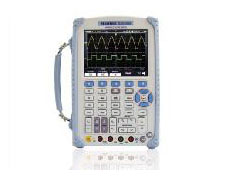
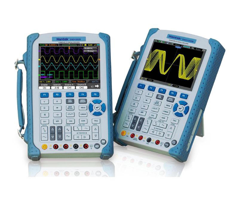
DSO1102B oscyloskop cyfrowy 2 x 100MHz

Seria DSO1000B
Oscyloskopy przenośne serii DSO1000B występują w pasmach 60MHz -200MHz. Próbkowanie 1GSa/s, długość rekordu pamięci 1M. Urządzenie posiada wbudowany miernik DMM umożliwiający pomiar parametrów elektrycznych (DMM), wbudowany bargraf. Kolorowy wyświetlacz TFT LCD 5,6" o rozdzielczości 640 x 480.
Cechy produktu
- model: DSO1102B
- szerokość pasma 100MHz
- częstotliwość próbkowania 1GSa/s
- multimetr cyfrowy DMM z bargrafem
- rekord pamięci 1M
- wysoka częstotliwość odświeżania 2500
- duży wyświetlacz TFT LCD o przekątnej 5,6". Rozdzielczość 640 x 480 pikseli.
- optymalne rozmieszczenie przycisków oraz funkcji
- proste czytelne menu
- 32 pomiary automatyczne
- funkcje matematyczne
- funkcja save/recall
- automatyczne kursory
- tryb XY
- wbudowana funkcja fft
- rejestracja przebiegów do przechwytywania, odtwarzania przebiegów z kanału 1 i 2 z maksymalną długością zapisu do 1000 ramek
- funkcja pass/fail
- tryb średniej do wygładzenia przebiegów
- złącze do kalibracji sond 2V 1kHz
- interfejs USB do obsługi pamięci USB,
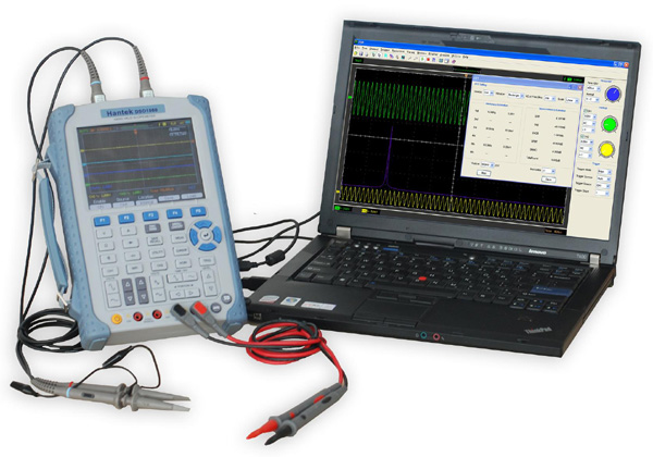
- możliwość obsługi przez komputer
- wymiary: 240 x 165 x 50 mm
- wbudowany akumulator
- niewielka waga
Przydatne linki
Oprogramowanie
Manual w języku angielskim
Sterowniki
▶ Podłączenie do komputera umożliwia obsługę oscyloskopu z poziomu oprogramowania
|
|
 |
 |
 |
 |
 |
 |
 |
 |
 |
 |
 |
 |
 |
 |
 |
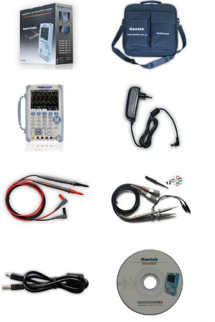
Zestaw zawiera
- 1 x oscyloskop cyfrowy DSO1102B
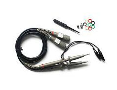
- 2 x sonda z dzielnikiem 1:1/1:10
- 1 x torba na akcesoria i oscyloskop
- 1 x zasilacz 12V
- 1 x zestaw przewodów pomiarowych do miernika
- 1 x kabel USB
| Model | DSO1202B | DSO1102B | DSO1062B |
| Acquisition | |||
| Sample Modes | Real-Time Sample: 1GS/s; Equivalent Sample: 25GS/s |
||
| Acquisition Modes | |||
| Normal | Normal data only | ||
| Peak Detect | High-frequency and randon glith capture | ||
| Average | Wavefom Average, selectable 4,8,16,32,64,128 | ||
| Inputs | |||
| Inputs Coupling | AC, DC, GND | ||
| Inpits Impendance | 1MΩ±2% ‖20pF±3pF | ||
| Probe Attenuation | 1X, 10X | ||
| Supported Probe Attenuation Factor | 1X, 10X, 100X, 1000X | ||
| Maximum Input Voltage | CAT I and CAT II: 300VRMS (10×), Installation Category; CAT III: 150VRMS (1×); Installation Category II: derate at 20dB/decade above 100kHz to 13V peak AC at 3MHz* and above. For non-sinusoidal waveforms, peak value must be less than 450V. Excursion above 300V should be of less than 100ms duration. RMS signal level including all DC components removed through AC coupling must be limited to 300V. If these values are exceeded, damage to the oscilloscope may occur. |
||
| Horizontal | |||
| Sample Rate Range | 500MS/s--1GS/s | ||
| Waveform Interpolation | (sin x)/x | ||
| Record Length | 1M | ||
| SEC/DIV Range | 2ns/div~2000s/div, | 4ns/div~2000s/div, | |
| Sample Rate and Delay Time Accuracy |
500ps(at over any ≥1ms time interval) | ||
| Position Range | 2ns/div to8ns/div; (-8div×s/div) to 20ms; |
4ns/div to 8ns/div; (-8div x s/div) to 40ms; 20ns/div to 80μs /div;(-8div×s/div)to 40ms; 200μs/div to 40s/div; (-8div×s/div)to 400s; |
|
| Delta Time Measurement Accuracy (Full Bandwidth) |
Single-shot, Normal mode:± (1 sample interval +100ppm × reading + 0.6ns); >16 averages:± (1 sample interval + 100ppm × reading + 0.4ns); Sample interval = s/div ÷ 200 |
||
| Vertical | |||
| Vertical Resolution | 8-bit resolution, all channel sampled simultaneously | ||
| Offset Range | 2mV/div to 20mV/div, ±400mV; 50mV/div to 200mV/div, ±2V; 500mV/div to 2V/div, ±40V; 5V/div, ±50V |
||
| Bandwidth | 200MHz | 100MHz | 60MHz |
| Rise Time at BNC( typical) | 1.8ns | 3.5ns | 5.8ns |
| Math | +, -, *, /, FFT | ||
| FFT | Windows: Hanning、Flatop、Rectamgular、Bartlett、Blackman; 1024 sample point | ||
| Bandwidth Limit | 20MHz | ||
| Low Frequency Response (-3db) | ≤10Hz at BNC | ||
| DC Gain Accuracy | ±3% for Normal or Average acquisition mode, 5V/div to 10mV/div; ±4% for Normal or Average acquisition mode, 5mV/div to 2mV/div |
||
| DC Measurement Accuracy, Average Acquisition Mode |
When vertical displacement is zero, and N ≥16:± (3% × reading + 0.1div + 1mV) only 10mV/div or greater is selected; When vertical displacement is not zero, and N≥16: ± [3% × (reading + vertical position) + 1% of vertical position + 0.2div]; Add 2mV for settings from 2mV/div to 200mV/div; add 50mV for settings from 200mV/div to 5V/div |
||
| Volts Measurement Repeatability, Average Acquisition Mode |
Delta volts between any two averages of ≥16 waveforms acquired under same setup and ambient conditions | ||
| Trigger | |||
| Trigger Types | Edge, Video, Pulse, Slope, Over time, Alternative | ||
| Trigger Source | CH1, CH2, AC Line | ||
| Trigger Modes | Auto, Normal | ||
| Coupling Type | DC, AC, Noise Reject, HF Reject, LF Reject | ||
| Trigger Sensitivity (Edge Trigger Type) |
DC(CH1,CH2): 1div from DC to 10MHz; 1.5div from 10MHz to 100MHz; 2div from 100MHz to Full; AC: Attenuates signals below 10Hz ; HF Reject: Attenuates signals above 80kHz; LF Reject: Same as the DC-coupled limits for frequencies above 150kHz; attenuates signals below 150kHz |
||
| Trigger Level Range | CH1/CH2: ±8 divisions from center of screen; | ||
| Trigger Level Accuracy( typical)Accuracy is for signals having rise and fall times ≥20ns | CH1/CH2: 0.2div × volts/div within ±4 divisions from center of screen; | ||
| Set Level to 50%(typical) | Operates with input signals ≥50Hz | ||
| Video Trigger | |||
| Video Trigger Type | CH1, CH2: Peak-to-peak amplitude of 2 divisions; | ||
| Signal Formats and Field Rates, Video Trigger Type | Supports NTSC, PAL and SECAM broadcast systems for any field or any line | ||
| Holdoff Range | 100ns ~ 10s | ||
| Pulse Width Trigger | |||
| Pulse Width Trigger Mode | Trigger when (, = , or ≠); Positive pulse or Negative pulse | ||
| Pulse Width Trigger Point | Equal: The oscilloscope triggers when the trailing edge of the pulse crosses the trigger level. Not Equal: If the pulse is narrower than the specified width, the trigger point is the trailing edge. Otherwise, the oscilloscope triggers when a pulse continues longer than the time specified as the Pulse Width. Less than: The trigger point is the trailing edge. Greater than (also called overtime trigger): The oscilloscope triggers when a pulse continues longer than the time specified as the Pulse Width |
||
| Pulse Width Range | 20ns ~ 10s | ||
| Slope Trigger | |||
| Slope Trigger Mode | Trigger when ( , = , or ≠ ); Positive slope or Negative slope | ||
| Slope Trigger Point | Equal: The oscilloscope triggers when the waveform slope is equal to the set slope. Not Equal: The oscilloscope triggers when the waveform slope is not equal to the set slope. Less than: The oscilloscope triggers when the waveform slope is less than the set slope. Greater than: The oscilloscope triggers when the waveform slope is greater than the set slope. |
||
| Time Range | 20ns ~ 10s | ||
| Overtime Trigger | |||
| Over Time Modee | Rising edge or Falling edge | ||
| Time Range | 20ns ~ 10s | ||
| Alternative Trigger | |||
| Trigger on CH1 | Internal Trigger: Edge, Pulse Width, Video, Slope | ||
| Trigger on CH2 | Internal Trigger: Edge, Pulse Width, Video, Slope | ||
| Trigger Frequency Counter | |||
| Readout Resolution | 6 digits | ||
| Accuracy (typical) | ±30ppm (including all frequency reference errors and ±1 count errors) | ||
| Frequency Range | AC coupled, from 4Hz minimum to rated bandwidth | ||
| Signal Source | Pulse Width or Edge Trigger modes: all available trigger sources The Frequency Counter measures trigger source at all times, including when the oscilloscope acquisition pauses due to changes in the run status, or acquisition of a single shot event has completed. Pulse Width Trigger mode: The oscilloscope counts pulses of significant magnitude inside the 1s measurement window that qualify as triggerable events, such as narrow pulses in a PWM pulse train if set to < mode and the width is set to a relatively small time. Edge Trigger mode: The oscilloscope counts all edges of sufficient magnitude and correct polarity. Video Trigger mode: The Frequency Counter does not work. |
||
| Measure | |||
| Cursor Measurement | Voltage difference between cursors: △V Time difference between cursors: △T Reciprocal of △T in Hertz (1/ΔT) |
||
| Auto Measuerment | Frequency, Period, Mean, Pk-Pk, Cycli RMS, Minimum, Maximum, Rise time, Fall Time, +Pulse Width, -Pulse Width, Delay1-2Rise, Delay1-2Fall, +Duty, -Duty, Vbase, Vtop, Vmid, Vamp, Overshoot, Preshoot, Preiod Mean, Preiod RMS, | ||
| General Features | |||
| Display | |||
| Display Resolution | 640 horizontal by 480 vertical pixels | ||
| Display Contrast | Adjustable (16 gears) with the progress bar | ||
| Probe Compensator Output | |||
| Output Voltage( typical) | About 5Vpp into ≥1MΩ load | ||
| Frequency(typical) | 1kHz | ||
| Power Supply | |||
| Supply Voltage | AC Input:100-240VACRMS,0.6A MAX,50Hz~60Hz; DC Output:9V,2A | ||
| Power Consumption | <30W | ||
| Environmental | |||
| Temperature | Operating: 32℉ to 122℉ (0℃ to 50℃); Nonoperating: -40℉ to 159.8℉ (-40℃ to +71℃) |
||
| Cooling Method | Convection | ||
| Humidity | +104℉ or below (+40℃ or below): ≤90% relative humidity; 106℉ to 122℉ (+41℃ to 50℃): ≤60% relative humidity |
||
| Altitude | Operating: Below 3,000m (10,000 feet); Nonoperaring: Below 15,000m(50,000 feet) |
||
| Mechanical | |||
| Size | Length 245mm; Width 163mm; Height 52mm | ||
| Weight | 2.8KG(with Packing); 1.2KG(without Packing) | ||
| DMM Mode | |||
| Max. Resolution | 6000 Counts | ||
| DMM Testing Modes | Voltage, Current, Resistance, Capacitance, Diode & Continuity | ||
| Max. Input Voltage | AC:600V, DC: 800V | ||
| Max. Input Current | AC: 10A, DC:10A | ||
| Input Impedance | 10MΩ | ||
| DMM TrendPlot | 1.2M Point | ||
| Range | Resolution | Accuracy | Resolution |
| DC Voltage | 60.00mV | ±1%±3 digit | 10uV |
| 600.0mV | 100uV | ||
| 6.000V | 1mV | ||
| 60.00V | 10mV | ||
| 600.0V | 100mV | ||
| 800V | 1V | ||
| AC Voltage | 60.00mV | ±1%±3 digit | 10uV |
| 600.0mV | 100uV | ||
| 6.000V | 1mV | ||
| 60.00V | 10mV | ||
| 600.0V | 100mV | ||
| DC Current | 60.00mA | ±1%±5 digit | 10uA |
| 600.0mA | ±1.5%±5 digit | 100uA | |
| 6.000A | 1mA | ||
| 10.00A | 10mA | ||
| AC Current | 60.00mA | ±1%±5 digit | 10uA |
| 600.0mA | ±1.5%±5 digit | 100uA | |
| 6.000A | 1mA | ||
| 10.00A | 10mA | ||
| Resistance | 600Ω | ±1%±3 digit | 0.1Ω |
| 6.000KΩ | 1Ω | ||
| 60.00KΩ | 10Ω | ||
| 600.0KΩ | 1KΩ | ||
| 6.000MΩ | 10KΩ | ||
| 60.00MΩ | ±1%±5 digit | 100KΩ | |
| Capacitance | 40.00nF | ±2%±5 digit | 10pF |
| 400.0nF | 100pF | ||
| 4.000uF | 1nF | ||
| 40.00uF | 10nF | ||
| 400.0uF | 100nF | ||
| Attention: the smallest capacitance value that can be measured in 5nF | |||
| Diode | 0V~2.0V | ||
| ON-OFF test | <10Ω | ||
Nikt jeszcze nie napisał recenzji do tego produktu. Bądź pierwszy i napisz recenzję.
Tylko zarejestrowani klienci mogą pisać recenzje do produktów. Jeżeli posiadasz konto w naszym sklepie zaloguj się na nie, jeżeli nie załóż bezpłatne konto i napisz recenzję.

DSO1062B oscyloskop cyfrowy 2 x 60MHz
1 985,00 zł